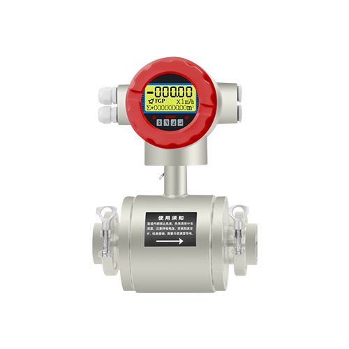
Electromagnetic Flow Meter
Commonly Measured Media
Domestic sewage, industrial wastewater, slurry, pulp, seawater, acid-base solution, clarified lime water, conductive liquid medium
Product Overview
The measurement principle of electromagnetic flowmeters is based on Faraday’s law of electromagnetic induction. The measuring tube of the flowmeter is a short tube made of non-magnetic alloy lined with insulating material. Two electrodes penetrate the tube wall along the diameter and are fixed on the measuring tube, with their electrode tips basically flush with the inner surface of the lining. When the excitation coil is excited by a double rectangular wave pulse, a working magnetic field with a magnetic flux density of B will be generated in a direction perpendicular to the axis of the measuring tube.
When a fluid with a certain conductivity flows through the measuring tube, it cuts the magnetic field lines and induces an electromotive force E, which is proportional to the product of the magnetic flux density B, the inner diameter d of the measuring tube, and the average flow velocity v. The electromotive force E (flow signal) is detected by the electrodes and transmitted to the converter via a cable. After the converter amplifies and processes the flow signal, it can display the fluid flow velocity and output signals such as pulses and analog currents for Byte Flow Control and adjustment.
Standard: JB/T9248-2015
Flange Standard: GB/T9119-2010
Measurement Principle
According to Faraday’s law of electromagnetic induction, a pair of detection electrodes are installed on the tube wall perpendicular to both the axis of the measuring tube and the magnetic field lines. When the conductive liquid moves along the axis of the measuring tube, the conductive liquid cuts the magnetic field lines to generate an induced electromotive force, which is detected by the two detection electrodes. The magnitude of this induced electromotive force is proportional to the flow rate, and its value is: E = KBVD
In the formula:
E – Induced electromotive force; D – Electrode spacing (inner diameter of the measuring tube); B – Magnetic induction intensity; V – Average flow velocity of the conductive liquid; K – Coefficient related to magnetic field distribution and axial length.
The sensor takes the induced electrothermal E as the flow signal and transmits it to the converter. After amplification, transformation, filtering, and a series of digital processing, the instantaneous flow and cumulative flow are displayed on a dot matrix liquid crystal display with backlight. The converter has 4-20mA output, upper and lower limit alarm output, and frequency output, and is equipped with communication interfaces such as RS-485 and the Hart protocol.
Product Features
- · The measuring tube has no flow-blocking components, with zero pressure loss and is not prone to clogging.
- ·As long as the electrode and lining materials are properly selected, the requirements for corrosion resistance and wear resistance can be met.
- · The measurement results are basically independent of physical parameters such as the pressure, temperature, density, viscosity, and conductivity (not less than the minimum conductivity) of the liquid, and are not affected by the environment, so
- High measurement accuracy, stable operation, and reliability.
- ·Utilizes modern analog signal conversion technology and high-performance very large scale integrated (VLSI) chips to isolate, filter, amplify, and digitally process signals. Accurately displays measurement results.
- · Automatically monitors and corrects parameters that affect measurement results, such as zero drift correction, and sets and corrects segmented flow coefficients across the full range, thereby expanding the measurement range, enhancing the level of intelligence and measurement accuracy, and greatly improving stability performance.
- ·It has the functions of power-off protection for measured values and over-range alarm, and can set the flow direction of the fluid inside the sensor. Therefore, the installation of the sensor is not restricted by the liquid flow direction, enabling bidirectional flow measurement.
- · Adopts a backlit dot matrix double-row flow display that simultaneously shows instantaneous flow, cumulative flow, and can display working status, parameters, measurement units, etc.
- ·Electromagnetic flowmeters have a wide range of measurement (maximum flow/minimum flow), with a normal applicable range of 20:1, generally 30:1 or greater.
- · The instrument is configured with multiple output functions, can be used in conjunction with computers and unit combination instruments, and can meet the requirements for printing, communication, and networking.
Product Parameters
| Nominal Diameter DN (mm) | DN10-DN1500 |
| Flow Direction | Positive, negative, and net flows; |
| lining | PTFE DN10 – DN500; Rubber DN50 – DN1500 |
| Connection Method | Flange type; Clamp type; Thread type; Split type; |
| Show | Non-display type; LCD display type |
| Liquid flow rate range (m³/h) | 0.13~ 5100m³/h |
| Range ratio | 1:10; |
| Body Material | SS304; SS316L (customization required) |
| Accuracy Class | Class 0.2; Class 0.5; Class 1.0; Repeatability error: 0.1% |
| Lining Temperature | Ordinary rubber -20~+70℃; High-temperature rubber lining -20~+90℃; Polytetrafluoroethylene lining -20~+120℃; High-temperature type polytetrafluoroethylene lining -20~+150℃; |
| Rated Working Pressure | Pressure resistance 0.6MPa – 4MPa (high pressure can be customized) |
| Conductivity Range | The conductivity of the fluid being measured is ≥20us/cm (integrated type), and the conductivity of water is in the range of 200-800us/cm |
| Signal Output | 4-20mA; Pulse; RS485 |
| Digital Frequency Output | The maximum collector current is 250mA, the output frequency range is 1 to 5000HZ, and the external power supply ≤35V |
| Power Supply | 85-265V/45-63HZ,DC24V |
| Installation of straight pipe section length | Upstream ≥ 10DN, downstream ≥ 5DN; |
| Explosion-proof Marking | Exd[ia]IICT6 |
| Protection Class | IP65, customizable to high IP68 |
| Environmental Conditions | Temperature -25°C to 60°C; relative humidity 5% to 90% |
| Total power consumption: | Less than 20W |
Lining Material Description
| Name | Main Performance | Maximum medium temperature | Scope of Application |
| Neoprene | 1. Good elasticity, high tensile strength, and excellent wear resistance. 2. Resistant to corrosion by common low-concentration acid, alkali, and salt media, as well as oxidative media. | Supports customizable temperature from 70°C to 120°C | Water, sewage, weakly abrasive slurries, and pulp |
| Polyurethane Rubber | 1. Good wear resistance 2. Poor acid and alkali corrosion resistance | 90℃ | Neutral, highly abrasive mineral slurries, coal slurries, and muds |
| Polytetrafluoroethylene (PTFE) | 1. It can withstand most chemical media, including boiling hydrochloric acid, sulfuric acid, nitric acid, and water, as well as concentrated alkalis and various solvents; it is not resistant to corrosion by chlorine trifluoride, high-temperature oxygen trifluoride, high-velocity liquid fluorine, liquid oxygen, and ozone. 2. Its abrasion resistance is inferior to that of polyurethane rubber, and its negative pressure resistance is inferior to that of neoprene rubber. | 120℃ – 150℃, custom temperature supported | Strongly corrosive media, such as concentrated acids and strong alkalis, as well as hygienic media |
| Perfluoroethylene Propylene Copolymer | 1. It is not resistant to fuming nitric acid and butyllithium; other chemical properties are basically the same as those of polytetrafluoroethylene. <br>2. Its negative pressure resistance is higher than that of polytetrafluoroethylene. | 120℃ – 150℃, custom temperature supported | Strongly corrosive media, such as concentrated acids and strong alkalis, as well as hygienic media |
Description of Electrode/Grounding Material
| Material | Corrosion resistance |
| Molybdenum-containing stainless steel (0Cr18Ni12Mo2Ti) | Nitric acid, sulfuric acid <5% at room temperature, boiling phosphoric acid, acetic acid, alkaline solution, sulfurous acid under a certain pressure, seawater, ±0.1% acetic acid. |
| Hastelloy C / Hastelloy B (HC, HB) | Resistant to oxidizing acids, oxidizing salts, seawater, non-oxidizing circulating acids, non-oxidizing salts, alkalis, and sulfuric acid at room temperature. |
| Titanium (Ti) | Seawater, various chlorides and hypochlorous acid, chloric acid (including fuming nitric acid), organic acids, and alkalis. |
| Tantalum (Ta) | Applicable scope: Most acidic solutions, such as concentrated hydrochloric acid, nitric acid, sulfuric acid, including hydrochloric acid and nitric acid at boiling point and sulfuric acid below 175°C <br> Not applicable scope: Alkalis, hydrofluoric acid, fuming sulfuric acid. |
| Platinum (Pt) | Various acids, alkalis, salts, except aqua regia |
Insertion Electromagnetic Flowmeter Parameters
| Nominal Pipe Size DN (mm) | DN100~DN3000 |
| Liquid flow rate range (m³/h) | 0.13~ 6000m³/h |
| Flow rate measurement range | 0~1m/s to 0~10m/s, with a full-scale range of 1~10m/s |
| Measurement accuracy | 1.5 Level |
| Work pressure | 1.6Mpa |
| Electrode Material | Molybdenum-containing stainless steel 0Cr118Ni12Mo2Ti, Hastelloy C-276, Titanium Ti, etc. |
| Measuring tube material | Polytetrafluoroethylene |
| Temperature of the measured medium | 0℃~60℃ |
| Enclosure Protection Rating | IP65;IP68 |
| Communication Function | RS485 Modbus RTU Protocol |
Flow Range
| Path | Minimum Flow Selection | Commonly Used Full-Scale Flow Selection (m3/h) |
| 4 | 0.01 | 0.05、0.1、0.2、0.25 |
| 10 | 0.10 | 0.4、0.5、0.6、0.8、1.0、1.6、2.0、2.5 |
| 15 | 0.20 | 1.0、1.2、1.6、2.0、2.5、3.0、4.0、5.0、6.0 |
| 20 | 0.35 | 2.0、2.5、3.0、4.0、5.0、6.0、8.0、10.0、12.0 |
| 25 | 0.55 | 3.0、4.0、5.0、6.0、8.0、10.0、12.0、14.0、16.0 |
| 32 | 1.0 | 5.0、6.0、8.0、10.0、12.0、16.0、20.0、25.0 |
| 40 | 1.5 | 8.0、10.0、12.0、16.0、20.0、25.0、30.0、40.0 |
| 50 | 2.5 | 12、16、20、25、30、40、50、60、70 |
| 65 | 4.0 | 20、25、30、40、50、60、80、100、120 |
| 80 | 5.5 | 25、30、40、50、60、80、100、120、160 |
| 100 | 8.5 | 40、50、60、80、100、120、160、200、250 |
| 125 | 14 | 60、80、100、120、160、200、250、300、400 |
| 150 | 20 | 100、120、160、200、250、300、400、500、600 |
| 200 | 35 | 160、200、250、300、400、500、600、800、1000 |
| 250 | 55 | 200、250、300、400、500、600、800、1000、1200、1600 |
| 300 | 80 | 300、400、500、600、800、1000、1200、1600、2000、2500 |
| 350 | 105 | 400、500、600、800、1000、1200、1600、2000、2500、3000 |
| 400 | 135 | 500、600、800、1000、1200、1600、2000、2500、3000、4000 |
| 450 | 175 | 600、800、1000、1200、1600、2000、2500、3000、4000、5000 |
| 500 | 215 | 800、1000、1200、1600、2000、2500、3000、4000、5000、6000 |
| 600 | 305 | 1000、1200、1600、2000、2500、3000、4000、5000、6000、10000 |
| 700 | 415 | 1200、1600、2000、2500、3000、4000、5000、6000、10000、12000 |
| 800 | 545 | 1600、2000、2500、3000、4000、5000、6000、10000、12000、16000 |
| 900 | 690 | 2000、2500、3000、4000、5000、6000、10000、12000、16000、20000 |
| 1000 | 850 | 2500、3000、4000、5000、6000、10000、12000、16000、20000、25000 |
| Other large-caliber products can be customized | ||
For flow meters, the medium flow velocity is generally suitable at 2 – 6 m/s, with a special minimum not less than 0.3 m/s and a maximum not exceeding 12 m/s. If the flow velocity is too low, the electromagnetic signal will decrease, resulting in a decline in measurement accuracy. If the fluid contains solid particles, the flow velocity should be less than 3 m/s. For viscous liquids, a relatively higher flow velocity should be selected, which helps automatically remove contaminants on the electrodes and is also beneficial for improving measurement accuracy. The calculation formula for the relationship among flow rate, flow velocity, and caliber is as follows:
where Q: flow rate (m3/h)
V: Flow velocity (m/s)
D: Diameter (m)
After the caliber size of the flowmeter is determined, the full-scale value should be increased by (15% – 30%) based on the preset maximum process flow. In actual use, the flow rate shall not exceed the full-scale value. If it exceeds the full-scale value, the flow rate error in this part will be relatively large, and the normal accuracy range between the full-scale value and the minimum flow rate shall not exceed 20 times.
What are the ways to contact us?
You can get in touch with us via social media or fill out the contact form.