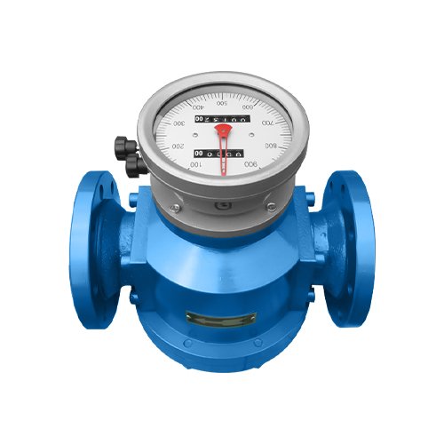
Elliptical Gear Flow Meter
Commonly Measured Media
Petroleum, diesel, resin, glue, asphalt, various emulsions, high-viscosity liquids
Product Overview
Elliptical gear flowmeters are positive displacement metering instruments specifically designed to measure and control the flow rate of liquids in pipelines. They are widely used in various industrial scenarios and can achieve continuous or intermittent metering and adjustment of liquid flow rates. With their outstanding performance, they have become the preferred equipment in the field of industrial fluid metering.
The core advantages of this flowmeter are prominent, featuring a wide measurement range, high metering accuracy, low fluid pressure loss, strong viscosity adaptability, etc. It can accurately measure high-temperature and high-viscosity liquids, with a simple calibration process and convenient installation, making it adaptable to various complex working conditions. Among them, the LC series oval gear flowmeter is equipped with a dual cumulative device of pointer and word wheel, which can directly display the cumulative flow and instantaneous flow of the liquid flowing through the pipeline on-site, with intuitive readings and convenient operation, and can be put into use without complex debugging.
To meet the requirements of large-scale and automated control, this flowmeter can be equipped with a signal device on the counting mechanism, which can be used in conjunction with various electric meters and instruments to achieve flow accumulation, quantitative control, and remote centralized monitoring of instantaneous flow, thereby facilitating the realization of automated monitoring and adjustment in industrial production and improving production efficiency. For the special metering requirements of high-temperature and high-viscosity liquids, the adaptability of the equipment can be optimized by installing a radiator or adopting the design of the lower teeth of the oval wheel to ensure stable and accurate metering performance even under extreme operating conditions.
Considering the differences in the characteristics of media across different industries, the main materials of flow meters can be flexibly selected based on the type of the measured liquid. For liquids with different corrosive properties or characteristics such as acids, alkalis, salts, and organic solutions, appropriate materials are selected for manufacturing, effectively improving the corrosion resistance and service life of the equipment, avoiding measurement deviations or equipment damage caused by media erosion, and meeting the fluid metering needs of multiple industries such as chemical, petroleum, and pharmaceutical.
Working Principle
The core of the oval gear flowmeter consists of two parts: the flow transmitter and the counting mechanism. For high-temperature working conditions, a radiator can be installed between the transmitter and the counting mechanism to form a high-temperature oval gear flowmeter. Among them, the flow transmitter is the metering core, consisting of a metering chamber with a pair of precision oval gear rotors inside and a sealed coupling; the counting mechanism is responsible for signal processing and flow display, including a reduction mechanism, an adjustment mechanism, a counter, and a signal transmitter, to achieve rotation conversion and flow reading.
This flowmeter is based on the volumetric (positive displacement) measurement principle, using the crescent-shaped chamber in the metering chamber as a fixed flow measurement unit – the metering chamber is precisely enclosed and formed by a pair of intermeshing oval gears and a cover plate, and its volume is calibrated through precision machining to ensure measurement accuracy.
The core logic of the measurement process is “pressure difference drive – volume capture – rotary transfer – flow conversion”, and the specific process is as follows: When the fluid flows through the flowmeter, a natural pressure difference (inlet pressure is greater than outlet pressure) will be generated between the inlet and outlet of the flowmeter. This pressure difference will exert a continuous driving force on the oval gears, pushing a pair of oval gears to mesh with each other and rotate in opposite directions at a constant speed. During the rotation of the gears, the liquid on the inlet side will be continuously captured into the crescent-shaped chamber. As the gears continue to rotate, the metering liquid in the chamber is smoothly transported to the outlet side, completing one metering measurement.
Through precise calibration, it is known that for each revolution of the elliptical gear, the volume of liquid passing through the metering chamber is fixed at four times the volume of a single crescent-shaped chamber (since the two gears alternately capture and transport, each gear completes two volume transports per revolution). The number of revolutions and rotational speed (corresponding to fluid flow velocity) of the elliptical gear are accurately transmitted to the counting mechanism through a sealed coupling: the reduction mechanism adapts and reduces the rotational speed, the adjustment mechanism calibrates the measurement accuracy, the counter accumulates the rotational speed and converts it into cumulative flow, the signal transmitter outputs a pulse signal, which is further converted into instantaneous flow, ultimately achieving accurate measurement and display of the cumulative flow and instantaneous flow of the liquid flowing through the pipeline.
Throughout the entire measurement process, the rotation of the oval gear is completely driven by the pressure difference between the inlet and outlet, eliminating the need for additional power. Moreover, the measurement accuracy is not affected by minor changes in the fluid flow velocity distribution or viscosity. The core lies in relying on the fixed volume of the crescent-shaped chamber and the precise transmission of gear rotation to ensure the stability and reliability of the measurement.
Product Parameters
| Instrument Caliber (mm) | DN10~DN200 |
| Accuracy Class | 0.5 level (0.2 level requires customization) |
| Range Ratio | 1:5;1:10 |
| Instrument Materials | Valve body: Cast iron, cast steel, stainless steel; Gear: Cast iron, stainless steel |
| Terms of Use | Ambient temperature: -20°C to +60°C; relative humidity: 5% to 90%; medium temperature: -20°C to +80°C; +100°C to +200°C |
| Working Power Supply | External power supply: 12/24VDC±15%, suitable for 4~20mA; pulse |
| Signal Output | Pulse; 4-20mA; RS485 |
| Connection Method | Flange; Thread |
| Protection Class | IP65 |
| Explosion-proof rating | Ex d IIC T6 Gb |
| Normal Flow Range/Product Parameters | ||
| Model | Cast Iron Type/Stainless Steel Type/Stainless Steel Type | |
| Accuracy Class | 0.5% | |
| Viscosity of the liquid being measured (mPa.s) | 200-1000mPa.s /1000-2000mPa.s | |
| Instrument Diameter (mm) | Flow range (m³/h) | |
| DN 10 | 0.16-0.4 | 0.08-0.4 |
| DN 15 | 0.6-1.5 | 0.3-1.5 |
| DN 20 | 0.75-3 | 0.6-3 |
| DN 25 | 1.5-6 | 0.8-6 |
| DN 40 | 5-15 | 3-15 |
| DN 50 | 6-24 | 4-24 |
| DN 65 | 8-40 | 8-40 |
| DN 80 (Light) | 8-40 | 8-40 |
| DN 80 (Heavy) | 15-60 | 10-60 |
| DN 100 | 30-100 | 15-100 |
| DN 150 | 45-190 | 34-190 |
| DN 200 | 68-340 | 56-340 |
| 4. High Viscosity Flow Range/Product Parameters | ||
| Model | LC-NA Cast Iron High Viscosity Type / LC-NE Cast Steel High Viscosity Type / LC-NB Stainless Steel High Viscosity Type | |
| Accuracy Class | 0.5% / 0.2% | |
| Viscosity of the measured liquid mPa.s | 200-2000 | |
| Instrument Caliber (mm) | Flow range (m³/h) | |
| DN 10 | 0.04-0.3 | 0.03-0.2 |
| DN 15 | 0.1-1.0 | 0.1-0.7 |
| DN 20 | 0.25-2.1 | 0.25-1.5 |
| DN 25 | 0.6-4.2 | 0.6-3 |
| DN 40 | 1.0-10.5 | 1.0-7.5 |
| DN 50 | 2-16.8 | 2-12 |
| DN 65 | 4-28 | 4-20 |
| DN 80 (Light) | 4-28 | 4-20 |
| DN 80 (Heavy) | 6-42 | 6-30 |
| DN 100 | 10-70 | 10-50 |
| DN 150 | 19-133 | 19-95 |
| DN 200 | 34-238 | 34-170 |
| 5. High-precision flow range/product parameters | ||
| Model | LC-A Cast Iron Type / LC-B Stainless Steel Type / LC-E Cast Steel Type | |
| Accuracy Class | 0.2% | |
| Viscosity of the measured liquid (mPa.s) | 0.6-200/2-200Pa.s | |
| Instrument Caliber (mm) | Flow range (m³/h) | |
| DN 10 | 0.2-0.4 | |
| DN 15 | 0.5-1.5 | |
| DN 20 | 1.5-3 | 1.2-3 |
| DN 25 | 3-6 | 1.6-6 |
| DN 40 | 8-15 | 6-15 |
| DN 50 | 12-24 | 8-24 |
| DN 65 | 20-40 | 13-40 |
| DN 80 (Light) | 20-40 | 13-40 |
| DN 80 (Heavy) | 30-60 | 20-60 |
| DN 100 | 50-100 | 30-100 |
| DN 150 | 90-190 | 68-190 |
| DN 200 | 170-340 | 112-340 |
What are the ways to contact us?
You can get in touch with us via social media or fill out the contact form.