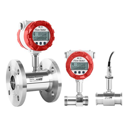
DW-LWGYA Intelligent Turbine Flowmeter
Commonly Measured Media
Liquids such as water, oil, and alcohols that are fiber-free, particle-free, low in corrosiveness, and free of impurities
Commonly Measured Media
Liquids such as water, oil, and alcohols that are fiber-free, particle-free, low in corrosiveness, and free of impurities
Product Overview
The DW-LWGYA series turbine flowmeter incorporates advanced technologies from domestic and international flow meters, and has been optimized through design. It features a simple and lightweight structure, high precision, good reproducibility, sensitive response, and convenient installation, maintenance, and operation. It is widely used to measure liquids with low corrosiveness and no impurities such as fibers or particles in closed pipelines. Liquids with a kinematic viscosity less than 5×10⁻⁶m2/s at operating temperature can be used directly, while for liquids with a kinematic viscosity greater than 5×10⁻⁶m2/s, the flowmeter can be calibrated with the actual liquid before use. When used in conjunction with a display instrument with special functions, it can also perform quantitative control, overrun alarm, etc., making it an ideal instrument for flow measurement and energy conservation.
Working Principle
Structure of Turbine Flow Sensor (Figure 1): When the fluid being measured flows through the sensor, under the action of the fluid, the impeller rotates under force, with its rotational speed proportional to the average flow velocity in the pipeline. The rotation of the impeller periodically changes the magnetic resistance of the magnetoelectric converter, causing the magnetic flux in the detection coil to change periodically, generating an induced electromotive force with the same frequency as the rotation frequency, i.e., an electrical pulse signal. After being amplified by an amplifier, it is sent to a display instrument for display.
The flow equation of the turbine flowmeter is:
qv = f / K (1)
qm = qvρ (2)
where qv, qm …… are volumetric flow rate, m3/s, and mass flow rate, kg/s, respectively;
f …… frequency of the flowmeter output signal, Hz;
K …… Meter coefficient of the flowmeter, P/m3.
The relationship curve between the coefficient of the flowmeter and the flow rate (or pipeline Reynolds number) (Figure 2) shows that the meter coefficient can be divided into two sections, namely the linear section and the nonlinear section. The linear section accounts for approximately two-thirds of its operating range, and its characteristics are related to the structural dimensions of the sensor and the fluid viscosity. In the nonlinear section, the characteristics are significantly affected by bearing friction and fluid viscous resistance. When the flow rate is below the lower limit of the sensor’s flow rate, the meter coefficient changes rapidly with the flow rate, and the pressure loss is approximately proportional to the square of the flow rate. When the flow rate exceeds the upper limit, attention should be paid to preventing cavitation. TUF characteristic curves with similar structures have similar shapes and only differ in terms of the level of systematic error.
Product Features
- a. Good repeatability, with short-term repeatability reaching 0.05% – 0.2%. Precisely because of its good repeatability, extremely high accuracy can be achieved through regular calibration or online calibration, making it a commonly selected flowmeter in trade settlement;
- b. High precision, generally up to ±1%R, ±0.5%R, and high-precision models can reach ±0.2%R;
- c. Outputs pulse frequency signals, with no zero-point drift and strong anti-interference ability;
- d. High-frequency signals (3 – 4kHz) can be obtained, with strong signal resolution;
- e. Wide rangeability, with medium and large diameters reaching 1:20 and small diameters being 1:10;
- f. Compact and lightweight structure, convenient installation and maintenance, large flow capacity;
- g. Suitable for high-voltage measurement, no need to drill holes on the meter body, easy to make into high-voltage type meters;
- h. Can be made into an insert type, suitable for large-diameter measurement, with low pressure loss, low cost, can be removed without interrupting the flow, and is convenient for installation and maintenance.
Product Parameters
| Instrument Caliber and Connection Method | 4, 6, 10, 15, 20, 25, 32, 40 use threaded connections (15, 20, 25, 32, 40); 50, 65, 80, 100, 125, 150, 200 use flange connections |
| Implementation Standard | Turbine Flow Sensor (JB/T9246-1999) |
| Accuracy Class | ±1%R, ±0.5%R, ±0.2%R (special production required) |
| Range Ratio | 1:10;1:15;1:20 |
| Instrument Material | 304 stainless steel, 316(L) stainless steel, etc. |
| Temperature of the measured medium (℃) | -20~+80℃;-20~+120℃;-20~+150℃; |
| Environmental Conditions | Temperature -10~+55℃, relative humidity 5%~90%, atmospheric pressure 86~106kPa |
| Output Signal | Sensor: Pulse frequency signal, low level ≤ 0.8V, high level ≥ 8V; Transmitter: Two-wire 4~20mADC current signal |
| Power Supply | A. External power supply: +24VDC±15%, ripple ≤±5%, suitable for 4-20mA, pulse output, R485, etc. B. Internal power supply: 1 set of 3.0V 10AH lithium battery, which operates normally when the battery voltage is between 2.0-3.0V |
| Signal Transmission Line | STVPV 3×0.3 (three-wire system), 2×0.3 (two-wire system) |
| Transmission Distance | ≤1000m |
| Signal Line Interface | Basic type: Hirschmann connector; Explosion-proof type: Internal thread M20×1.5 |
| Explosion-proof rating | ExdIICT6 |
| Protection Class | IP65 |
What are the ways to contact us?
You can get in touch with us via social media or fill out the contact form.