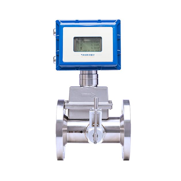
Gas Turbine Flow Meter
Commonly Measured Media
Compressed air, natural gas, nitrogen, coal gas, oxygen, methane, and other common gases Product Overview
Product Overview
The temperature and pressure compensated gas turbine flowmeter is an intelligent and precision metering instrument that integrates a gas turbine flow sensor and a flow converter into one. Relying on advanced ultra-low power consumption single-chip microcomputer technology and intelligent circuit design, it combines a built-in flow probe, microprocessor, temperature sensor, and pressure sensor, featuring a compact structure and high integration. Its main performance indicators have reached the international advanced level, making it an ideal choice for gas metering in various industries.
This flowmeter has been core-adapted specifically for gas metering scenarios. With its high-precision metering advantage, stable operating performance, and wide adaptability, it can be widely used in industries such as petroleum, chemical, power, and metallurgy, as well as gas metering for boilers. It is also suitable for high-precision metering demand scenarios such as urban natural gas transmission, gas pressure regulating station metering, and gas trade settlement. It not only meets the flow monitoring needs in industrial production process control but also ensures the fairness and accuracy of trade settlement.
This flowmeter has excellent technical characteristics, adopting a new impeller group design, with low starting flow, small pressure loss, excellent anti-vibration and anti-pulsating flow performance, and is equipped with wear-resistant self-lubricating precision bearings, which significantly reduces the frictional resistance of turbine rotation, reduces the metering drift caused by mechanical wear, and extends the service life while ensuring long-term measurement accuracy. Built-in high-precision temperature and pressure sensors can collect the working temperature and pressure of the measured gas in real time, automatically perform temperature and pressure compensation and compression factor correction through the gas state equation, convert the working volume flow rate into the standard state volume flow rate, completely eliminate the influence of temperature and pressure changes on the measurement results, with a measurement accuracy as high as ±0.5 to ±1.5 levels, a range ratio as high as 1:20, covering low, medium, and high flow rate ranges.
It features excellent operational and usage convenience, equipped with a liquid crystal display interface that can intuitively display parameters such as instantaneous flow rate under standard conditions, cumulative flow rate under standard conditions, flow rate under working conditions, as well as current medium temperature, pressure, etc., with clear and easy-to-read readings; it supports pulse output, 4~20mA analog signal output, and RS485 communication, and can be flexibly used in conjunction with computer control systems such as PLC and DCS to achieve remote transmission and centralized management and control of flow data. It also has the characteristic of ultra-low power consumption, adopting a dual-power supply mode, and allowing external power supply. Equipped with a complete self-diagnostic function and data power-off protection function, it is convenient for maintenance and debugging, effectively preventing data loss and further improving operational reliability.
Working Principle
Gas turbine flowmeter is a velocity-type flow measurement instrument with a simple and lightweight structure, high metering accuracy, good repeatability, wide measurement range, and convenient installation and maintenance. Its core operates based on the principle of conservation of angular momentum, capturing the rotation signal of the turbine driven by gas and combining with temperature and pressure compensation correction to achieve accurate metering of gas flow, which is widely used in various gas metering scenarios.
The specific measurement process is as follows: After the airflow enters the flowmeter, it first passes through a rectifier with a special structure and is accelerated to regularize the airflow state and ensure measurement accuracy. Under the action of the accelerated fluid, the turbine overcomes its own resistance torque and friction torque and begins to rotate. As the airflow continues to act, when the driving torque generated by the airflow balances the resistance torque and friction torque of the turbine, the rotational speed of the turbine tends to stabilize. At this time, within the rated range of the instrument, the rotational speed of the turbine is strictly proportional to the instantaneous flow rate of the gas, which is the core basis for flow conversion.
The acquisition and conversion of the rotational speed signal are achieved through a built-in signal transmission device: a rotating signal transmission disk is installed on the turbine, and the magnets on the signal transmission disk rotate synchronously with the turbine, periodically changing the surrounding magnetic field environment. This periodic change in the magnetic field triggers the pulse generator, causing it to output a pulse signal whose frequency is proportional to the gas flow rate (i.e., the turbine rotational speed), thus completing the conversion of “rotational speed – electrical signal”.
The pulse signal is then transmitted to the converter of the meter. The microprocessor in the converter performs operations such as counting, filtering, and amplification on the received pulse signal, directly converting it to obtain the working condition volume flow rate of the measured gas. Meanwhile, the converter synchronously detects the real-time temperature and pressure of the medium, accurately converts the working condition volume flow rate to the volume flow rate under standard conditions based on the standard volume correction model, and simultaneously accumulates the standard volume flow rate, ultimately obtaining the total standard volume, completely eliminating the influence of temperature and pressure changes on measurement accuracy.
Product Parameters
| Connection Method | Flange connection |
| Signal Output | Pulse signal, 4-20mA current signal, RS485 communication |
| Accuracy Class | Level 1.0, Level 1.5 |
| Instrument Materials | 304 Stainless Steel/Aluminum Alloy |
| Medium Temperature | -20℃~+60℃ |
| Terms of Use | Ambient temperature: -25~+80℃; |
| Relative Humidity | 5~95%; |
| Working Power Supply | 3.6V Lithium Battery, 24VDC |
| Explosion-proof rating | Exd II CT6 Gb |
| Protection Class | IP65 |
| Pressure Rating | 1.6 MPa, 2.5 MPa, 4 MPa, 6 MPa |
Flow Range
| Instrument Caliber (mm) | Normal flow range (m³/h) | Maximum Pressure Loss (kPa) |
| 25 | 4~40 | 1.5 |
| 40 | 6~65 | 1.5 |
| 50 | 7~70 | 0.5 |
| 50 | 10~100 | 1.0 |
| 80 | 13~250 | 1.0 |
| 80 | 20~400 | 2.5 |
| 100 | 20~400 | 1.0 |
| 100 | 32~650 | 1.5 |
| 150 | 50~1000 | 1.0 |
| 150 | 80~1600 | 2.0 |
| 200 | 80~1600 | 0.5 |
| 200 | 130~2500 | 1.0 |
| 250 | 130~2500 | 0.5 |
| 250 | 200~4000 | 1.5 |
| 300 | 200~4000 | 1.0 |
| 350 | 400~8000 | 1.5 |
| 400 | 650~13000 | 2.0 |
| *Maximum pressure loss refers to the pressure loss of the flowmeter when operating at the maximum flow point, with the medium being normal temperature air. Customizable: Class 1.0 | ||
What are the ways to contact us?
You can get in touch with us via social media or fill out the contact form.