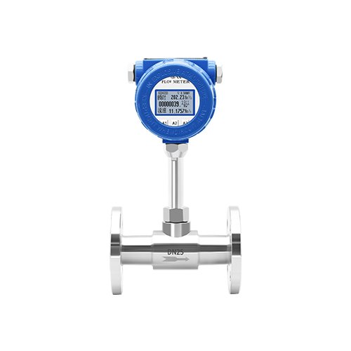
DW-LRF Thermal Gas Flow Meter
Commonly Measured Media
Compressed air, oxygen, nitrogen, hydrogen, argon, gases, and other gases
Product Overviewe
Thermal gas mass flow meters are designed based on the principle of thermal diffusion as the core foundation, using the constant temperature difference measurement method, which can directly and accurately measure gas flow without the need for additional temperature and pressure compensation devices, fundamentally ensuring the accuracy and convenience of metering data.
Thermal gas mass flow meters are based on the principle of thermal diffusion and use the constant temperature difference measurement method, which can directly and accurately detect the mass flow of gas without the need for additional temperature and pressure compensation devices, fully ensuring the accuracy of measurement and the convenience of use.
The product is compact in size, capable of flexibly adapting to various narrow installation scenarios; it has a high degree of digitization, with efficient data processing, clear display, facilitating system integration and remote control; it is easy to install, requiring no pipe cutting or complex debugging, which can significantly reduce on-site construction and maintenance costs; it has high measurement accuracy and strong anti-interference ability, capable of stably meeting the gas metering requirements under various working conditions.
This flowmeter is widely used in industries such as petrochemicals, power, municipal, environmental protection, and biomedicine, and can reliably monitor the instantaneous and cumulative flow rates of various dry gases such as air, nitrogen, natural gas, and flue gas. With its stable performance and convenient operation, it has become the preferred device for fine industrial Byte Flow Control.
Working Principle
The sensor part of the thermal gas mass flowmeter consists of two reference-grade platinum resistance temperature sensors. During operation, one sensor continuously measures the medium temperature T1; the other is self-heated to a temperature T2 higher than the medium temperature to sense the fluid flow velocity, which is defined as the velocity sensor.
The temperature difference is defined as T=T2−T1, where T2>T1. When fluid flows through, gas molecules collide with the sensor and take away heat from T2, causing its temperature to drop. To maintain a constant temperature difference T, the supply current for heating T2must be increased. The faster the gas flows, the more heat is dissipated. There is a fixed functional relationship between gas flow velocity and the supplementary heat quantity, which is the working principle of the constant temperature difference method.
The applicable medium temperature range of the thermal gas mass flowmeter is -10℃ ~ +200℃.
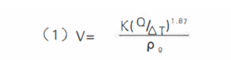
Conversion formula for fluid specific gravity and density related to mass calculation:

Where:
pg: Fluid specific gravity (correlated with density)
V: Medium flow velocityK: Balance coefficient
Q: Heating capacity (correlated with specific heat and structure)
Qm: Gas mass flow rate
T: Temperature difference
S: Cross-sectional area of the measuring pipe
The sensor temperature is automatically kept at a constant higher value (approximately 30~50℃) than the medium (ambient) temperature at all times. Therefore, thermal gas flowmeters require no temperature compensation in principle.

Pg: Medium density under working conditions (kg/m³)
P: Working pressure (kPa)
Pn: Medium density under standard conditions (101.325 kPa, 20℃) (kg/m³)
T: Working temperature (℃)
It can be seen from Formula (1), (2) and (3) that the functional relationships among flow velocity, working pressure, gas density and working temperature are determined. The constant temperature difference thermal gas mass flowmeter is affected neither by temperature nor by pressure. As a direct mass flowmeter, it requires no manual pressure and temperature correction by users.
Flow Range of Insertion Thermal Mass Flowmeter
The flow range of the insertion thermal mass flowmeter can be estimated according to the corresponding flow velocity range of 0.56~56 Nm/s. The calculation formula is as follows:
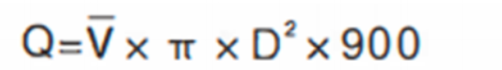
Where:
Q: Instantaneous flow rate in pipeline (Nm³/h)
V: Average flow velocity in pipeline (Nm/s)
S: Cross-sectional area of measuring pipe (m²)
Product Features
- No additional temperature and pressure compensation is required for gas flow measurement. It enables convenient and accurate measurement, and directly outputs gas mass flow or standard volume flow.
- It features a wide turndown ratio of over 100:1, suitable for gas detection. It has obvious advantages in large-diameter pipelines, low flow velocity, wide flow variation and ultra-low flow measurement.
- Excellent shock resistance; the measurement accuracy is not affected by vibration.
- Long service life. The sensor contains no moving parts or pressure sensing components, with simple installation and convenient maintenance.
- Fast response speed, low pressure loss and excellent repeatability.
- Adopting digital design with fully digital circuit measurement. The LCD display is intuitive and clear to ensure high measurement accuracy.
- Equipped with RS485 communication module or HART protocol, it supports centralized management by connecting with upper computer.
Product Parameters
| Structure | Plug-in, Pipe-type |
| Output signal | 4-20mA, Pulse, RS-485, HART Protocol |
| Flow Range | DN15 – DN80; 0.5~65 |
| Measuring Medium | Various gases (excluding acetylene gas) |
| Accuracy | ±1~2.5% |
| Sensor | -40~+160℃; |
| Converter | -20~+45℃ |
| Work Pressure | Medium pressure ≤ 2.5 MPa |
| Power Supply | DC 24V或AC220V ≤18W |
| Protection Class | IP65 |
Flow Range
| Pipe Diameter | Flow Range (Nm³/h) | Pipe Diameter | Flow Range (Nm³/h) |
| 15 | 0.5~65 | 100 | 3~2300 |
| 20 | 0.5~100 | 125 | 4.5~3500 |
| 25 | 0.5~175 | 150 | 6.5~5200 |
| 32 | 0.5~290 | 200 | 12~9000 |
| 40 | 0.5~450 | 250 | 18~14500 |
| 50 | 1~600 | 300 | 25~21000 |
| 65 | 1.5~1000 | 350 | 35~20000 |
| 80 | 2~1500 | 400 | 45~28000 |
What are the ways to contact us?
You can get in touch with us via social media or fill out the contact form.